Garrattfan's Modelrailroading Pages
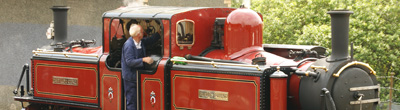
Fairlie Merddin Emrys
5.1 Bogie frames
Well at long last I got started. My previous projects all lasted several years, so be patient and follow along. Admittedly my AD60 still needs some work but I'll work on the Fairlie when I can't work on the AD60. The number in brackets in the text, like [2], refer to the numbered instructions in the restructured manual for the power bogie
|
|
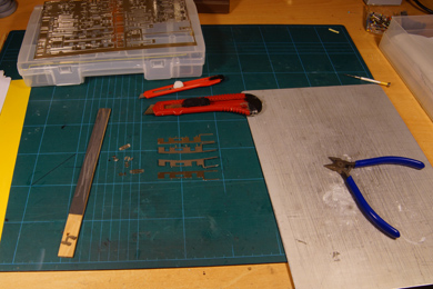
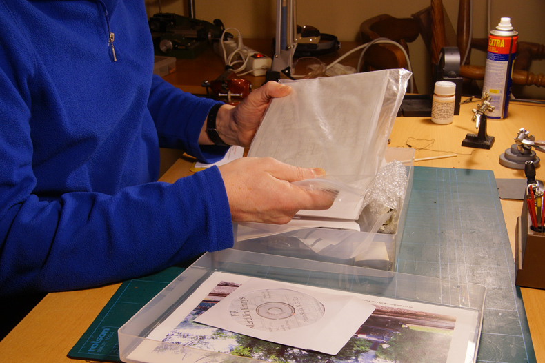
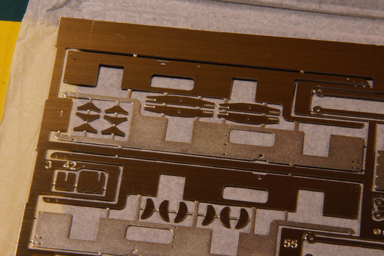
Unpacking the etch sheet. Oh boy at last I can start. |
|
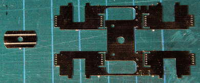
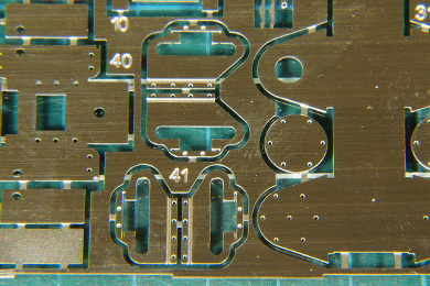
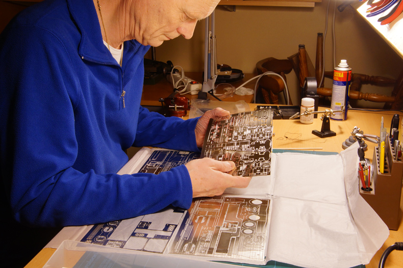
Studying the etch. |
|
Luckily most, but not all parts are numbered. |
|
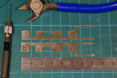
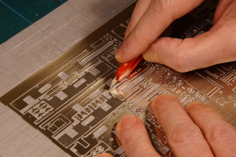
The first cut! The project now really has started! |
|
 |
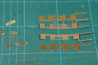
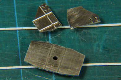
[1] After some cutting the first four parts lay on my desk. The manual is not very specific about it but each frame plate is built up from one full thickness plate and one half etched plate. I could find no particular detail justifying an etched wrapper, like nuts or rivets, so I must assume that the layering of the frame plates is simply for thickness.
|
 |
The half-etched frame plates curl a little. The nickel silver sheet is produced by rolling. The stresses in the sheet compensate each other and the full sheet lies flat. If you etch one half away the other half no longer get the counter pressure and tends to curl.
The parts left of the frame's components are parts that came loose with the cutting out of the frame. These will be stored in a sorting box for later use.
|
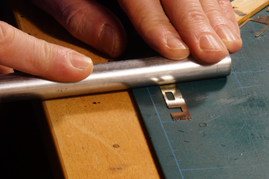 |
The curling is easily corrected by gently rolling the frame with a tube (be it brass or aluminium) until dead flat.
|
 |
[2] Soldering the two plates together. Although I found no obvious reason for handedness I made sure I had a left and a right hand frame.
|
 |
After soldering the edges were cleaned of cusps and etch tabs. I found a few spots were the solder hadn't taken hold and I re-soldered those spots. Filing the edges surely helped finding the trouble spots. |
 |
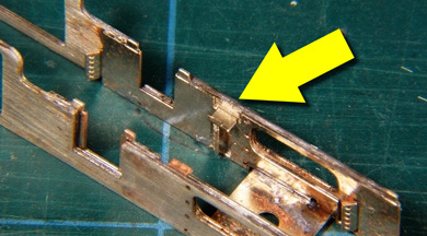
[4] The mid frame spacer (8). The part on the right was again one that come off as a by-effect and was stored for later |
 |
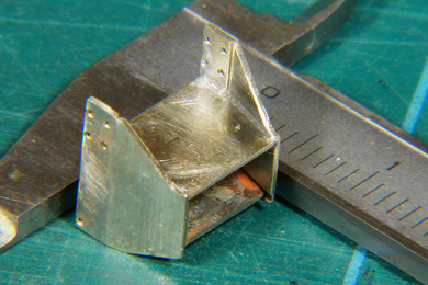
[7] Folding was easy |
 |
 |
The spacer was checked for squareness. The light passing from behind between the beam and the spacer is a very harsh judge. |
|
 |
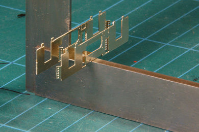
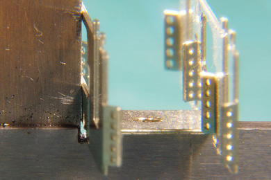
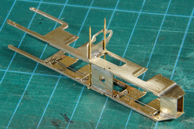
[8-9] Two pins held all together. As I do not have an engineers clamp as recommended. I tack soldered at the outer ends, left, right, top and bottom, and then in the middle, left right, top and bottom. After every tack I carefully checked if all was still sitting well. After the twelfth tack I started filling in. A quick pass with hot iron closed the gap between two tacks which I firmly held tight with a pair of pliers. The glass (a shelf from an old refrigerator) helped to continuously check if the frame was still straight. I allowed sufficient time to cool down after every pass so the heat would build up and distort the frame. |
During soldering, and just in time, I realised the intention of instruction [6]: "do not forget to bend out the two tabs for mounting the pickups". Errrrm, okay |
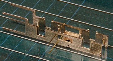
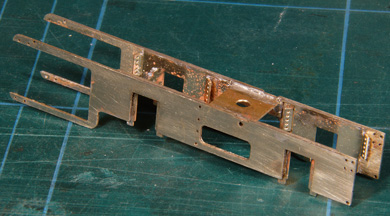
Done. After cleaning. |
The axles of the Fairlie are designed to have sprung bearings. The up and down movement of the bearing is minimal, no more than half a millimetre either side of horizontal but it has two effects.
|
|
 |
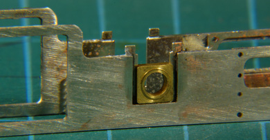 |
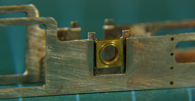
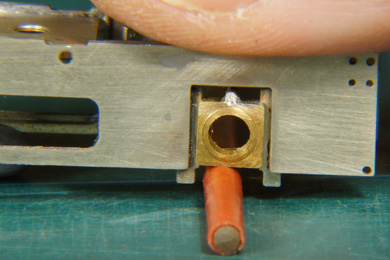
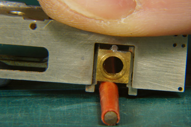
| [10] Trial fitting the bearing. They slid without any problem in their hornblocks. | |
|
The wire touched neither the bearing nor the axle. Now what? |
The instructions were not clear on how the springing of the bearings was to be arranged. I contacted EDM Models and Paul Martin was commendably supportive and provided me a drawing and the following instructions
Note: the instructions on the CD mention phosphor bronze wire for springing. Since the release of the kit some things have changed. This is one of them. Phosphor bronze loses its bounce so steel is a better springy wire.
DO NOT CUT this wire with a delicate flush cutter for brass. Ensure you use a cutter that can handle steel.
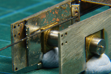
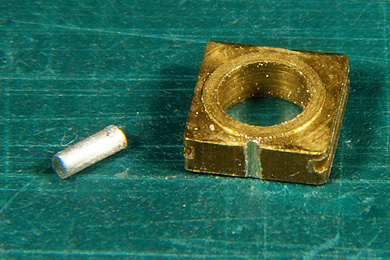
Getting the 0.9mm steel wire to size was a bit of a fiddle. To make things easier I made a few passes with my three square file on the top of the bearing. The steel wire will settle in the groove and you can press it down with the point of a knife blade to hold it in postion while soldering.
I made two choices
|
This is what Paul showed me to do. Once you have seen it, it is easy. |
|
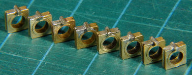
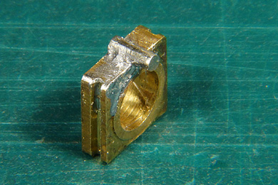
The grooved bearing and 2.5 mm length of steel wire cut, filed..... |
...and soldered. |
Up! |
And down! |
|
And down! |
Good, three more to go for this bogie and for more for the second bogie. I all did them in one stride, being at it anyway.
|
 |
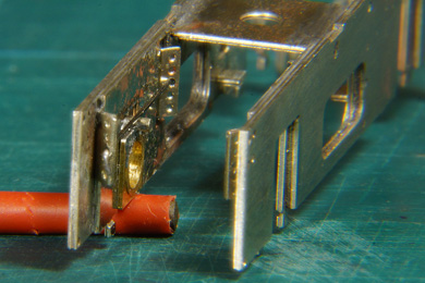
| Once done I put the frame on to alu profile to see if it all worked. I put this on a scale which I tared (setting it on zero with the weight of the frame on it). Then I pushed it slowly down until all four spungs were fully compressed. That was at a force of appr. 300 gram. Considerable! I admit it is a crude approximation but it is good enough. | 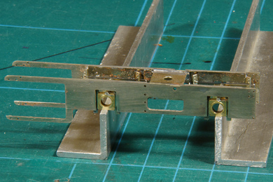 |
 |
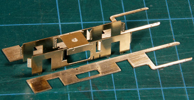
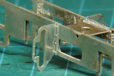
[12] Next job is on the rear frame stretcher. I chose the tapered version because I want to model Merddin Emrys as I saw it in 2009 and 2011. |
 |
After soldering I was proud because
|
 |
And what a joy when you trial fit the part in the frame. This is where the quality of the kit shows. Wonderfully accurate! |
 |
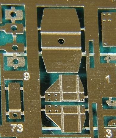
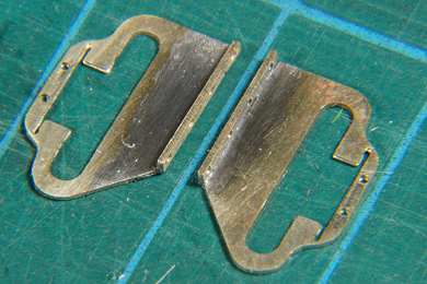
[15] Cutting out the motion brackets A few thing of note:.
I have no idea why I should drill holes. I drilled them anyway at 0.5 mm
|
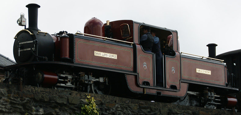
David Lloyd George passing Boston Lodge Works with a train to Blaenau showing four lubricators, 13 June 2009 16:06 |
|
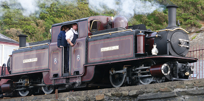
Less than fifteen minutes later Merddin Emrys passed the same location heading for Porthmadog. Only two lubricators are evident. I read by the way that four lubricators is the new standard. Merddin Emrys is currently (2016) disassembled for overhaul, so it possible that ME will reappear with four lubricators. |
|
 |
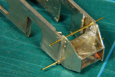
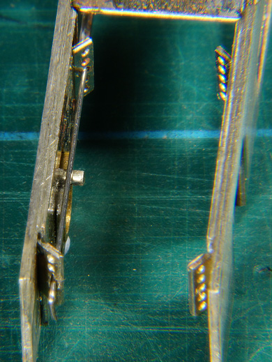
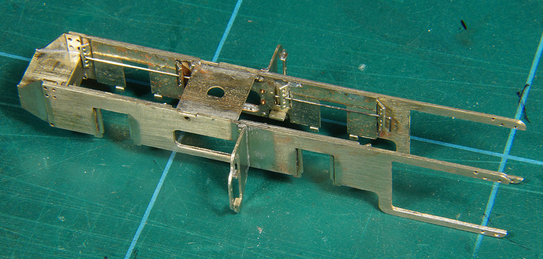
The motion brackets are drilled, folded and soldered with a fillet as per the instructions. Of course the brackets are decusped by careful filing |
 |
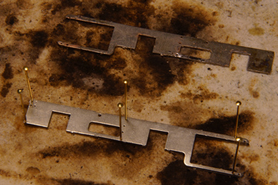
Using the 0.6mm brass pins to position the brackets is an ingenuous invention. It places the bracket super accurately and it releases one hand to do other necessary things. I first tack soldered the bracket in the middle, top and and bottom (in that order). Then I withdrew the pins to the point where they could be snipped off with a minimum of waste and ond then I gave it a complete pass of the soldering iron. |
 |
After soldering the pins are snipped off and filed down to a point where they could suggest heavy bolts. You can also file them flush if you like. |
One frame completed |
|

Sign my
GuestBook